
Steelrodeo
Well-Known Member
This is a procedure for those who brought a Modified Pico switch and want to add a remote LED to it or those who looking to buy a Pico switch and don’t want to dish out extra money for the remote LED.
I happened to like my LED on top of the controller box but you can place it any where you want. Just make wire the length you need. The material for LED light I selected can be found in any Radio Shack and they can order it for you if they don’t have it in stock. As for the wire, stick with the fine gauge wire that is flexible. You can use the wire from a dead or striped servo if you like.
If you are not experience, You Tube “how to solder deans” and get some tips on how to solder. The Pico switch is very small so practice first if you are not good at it.
Materials:
-Modified Pico switch
-Green LED (Radio Shack Part# 276-0027)
-Diode resistors 100ohm (Radio Shack Part# 271-1111)
-Wires (20 – 24 gauge)
-Shrink tube
Tools:
- Soldering iron with needle nose tip. You can use the spade tip if you are careful.
- Small table vise to hold the PC board.
- Solder
Cost: Under $4 if you have all the tools.
1. Remove the shrink wrap.
2. Orientate the board so that the controller wire is at the lower right hand corner (looking at the bottom). This is for you to get bearing on where the wire goes.
3. Mount the board on a small vise.
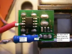
4. Attach positive wire to PC board (8 legs chip): Pre tins the wire and solder it to the (+) tab indicated in the picture. Make sure you don’t get any solder on the other tab. Don’t panic if you do. Just remove excess solder by cleaning the iron tip and drag solder away.
5. Attach the 100ohm resistor to the board (-) post: The other side of the negative tab is the black controller wire. Heat the tab and solder the resistor to it. The resistor lead was shortened to keep it neat. Resistor is not polar so and end will do.
Note: The 100 ohm resistor is spec out for the green LED bulb. Also make sure the resistor tab is cover with shrink tube so it does not touch the board.
6. Attach LED: Follow the picture for polarity. If it does not work, switch the wire around. You will not hurt the light.
7. Test the switch.
8. Once everything is ok, neatly bundle all the wires together and tie it with a zip tie. This is to strengthen the LED wire.
9. Wrap the switch Pico switch a couple times with electrical tape.
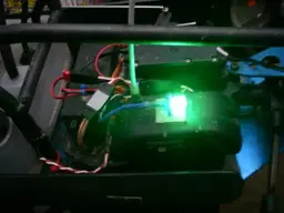
10. Attach the LED to the top of the controller box.
I hope this have enough detail for you. This project is not that difficult. It is fun and you will enjoy the result. The LED light is a blinder.
I happened to like my LED on top of the controller box but you can place it any where you want. Just make wire the length you need. The material for LED light I selected can be found in any Radio Shack and they can order it for you if they don’t have it in stock. As for the wire, stick with the fine gauge wire that is flexible. You can use the wire from a dead or striped servo if you like.
If you are not experience, You Tube “how to solder deans” and get some tips on how to solder. The Pico switch is very small so practice first if you are not good at it.
Materials:
-Modified Pico switch
-Green LED (Radio Shack Part# 276-0027)
-Diode resistors 100ohm (Radio Shack Part# 271-1111)
-Wires (20 – 24 gauge)
-Shrink tube
Tools:
- Soldering iron with needle nose tip. You can use the spade tip if you are careful.
- Small table vise to hold the PC board.
- Solder
Cost: Under $4 if you have all the tools.
1. Remove the shrink wrap.
2. Orientate the board so that the controller wire is at the lower right hand corner (looking at the bottom). This is for you to get bearing on where the wire goes.
3. Mount the board on a small vise.
4. Attach positive wire to PC board (8 legs chip): Pre tins the wire and solder it to the (+) tab indicated in the picture. Make sure you don’t get any solder on the other tab. Don’t panic if you do. Just remove excess solder by cleaning the iron tip and drag solder away.
5. Attach the 100ohm resistor to the board (-) post: The other side of the negative tab is the black controller wire. Heat the tab and solder the resistor to it. The resistor lead was shortened to keep it neat. Resistor is not polar so and end will do.
Note: The 100 ohm resistor is spec out for the green LED bulb. Also make sure the resistor tab is cover with shrink tube so it does not touch the board.
6. Attach LED: Follow the picture for polarity. If it does not work, switch the wire around. You will not hurt the light.
7. Test the switch.
8. Once everything is ok, neatly bundle all the wires together and tie it with a zip tie. This is to strengthen the LED wire.
9. Wrap the switch Pico switch a couple times with electrical tape.
10. Attach the LED to the top of the controller box.
I hope this have enough detail for you. This project is not that difficult. It is fun and you will enjoy the result. The LED light is a blinder.