Giant Half-Scale Build

This site may earn a commission from merchant affiliate
links, including eBay, Amazon, and others.
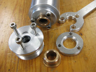
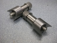
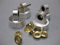
I added a bushing to the bottom cap as Allan suggested. There wasn't enough meat to put one in, so I added a retainer. All 3 diameters are a press fit and the screws give me something to put a wrench on to tighten the bottom caps;

IMG_3617.jpg


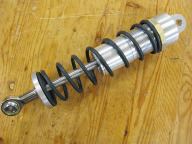
I also had 4 springs made up, just need to machine the spigots to keep them centred;

IMG_3616.jpg


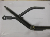
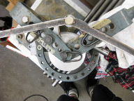
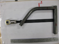
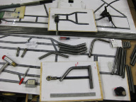
I started on the swing arms by setting my angle"O"meter to the template;

IMG_3559.jpg


Then mark the template with my bend gauge;

IMG_3554.jpg


Then mark the tube;

IMG_3555.jpg


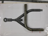
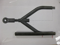
Then bend it to the angle;

gbt-ghm9bv29JiuSSI0MM5_-yMsi_XYSFKZ_xyKNZ-E=w675-h506-no.jpg


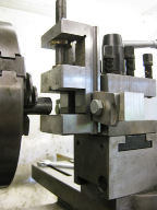
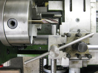
Here I am setting a vise in the tool post of the lathe to the correct height;

IMG_3578.jpg


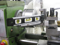
Set the tube level, and put a roughing end mill in the chuck;

IMG_3587.jpg


Bring the tube to the cutter;


IMG_3581.jpg


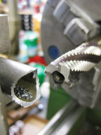
And here it is fish-mouthed;


IMG_3585.jpg


Mark to trim the excess;

IMG_3589.jpg


Rinse and repeat;

IMG_3590.jpg


Have fun out there! -Kevin
 
Thanks a lot J!


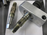
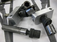
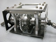
I hacked off the ends of the donor quad's rear axle and turned them down to fit my bearings and milled a square to be driven by the impact universal.

Note the difference in surface finish. I guess when you are cranking out thousands of these things, every second counts. ;)

Rear+axle+and+carrier+%25283%2529.jpg


I thought they would be to pretty tough to drill, so I sleeved the existing hole to take up the slack for the retaining screw, but I ended up drilling right through, so I could have drilled clean holes from the start...

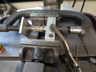
Here is the set-up to transfer the holes to the rear axle and have no end play;

rear+axle.jpg


And the assembled parts;

Rear+axle+and+carrier+%25281%2529.jpg


Happy bashing!

KB
 
Very impressive work mate.

This period I have an interest about Solidworks and start thinking to try with it. Maybe its not easy for old dogs but I like it.:w00t:


I have a little 'objection' to your suspension geometry.
The two arms are parallel and have the same lenght. I think that will make a ++ caber angle at the cornering, not the best for the holding.

Vass
 
Thank you Vass.

I was strictly pen and paper too, until a couple years ago. Once you get the hang of it, it really helps speed up the design process.

I am very limited in my steering/ suspension knowledge and appreciate your advice. I do not know what ++ camber means. What adjustments do you think I should make?

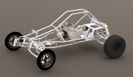
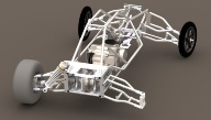
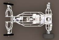
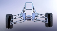
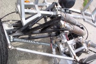
The rear swing arms are parallel and equal length. The front swing arms are parallel but unequal length. There has been a few adjustments since this picture was made but it is all I can post right now;

front+render+RC+Buggy.jpg


I have not yet welded any swing arm components, so I still have time to make some modifications.


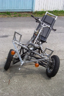
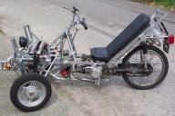
I have always gone with what feels and looks about right, like this trike I designed and built about 10 years ago. But now that I have computer modelling ability, it is great to try things in the computer first and seek advice from the community.

Thanks a lot for everyone's advice and encouragement!


100_1949.jpg Copy+of+100_1952.jpg

Copy+of+100_1948.jpg
 
A few suspansion's fundaments:

1. no parallel arms.
2.upper is about the 3/4 of down- arm's lenght.
3. the line between hub's joints, not vertical to the ground.

....and few pics to help more.


Uploaded with ImageShack.com


An example :

Two possitions, before cornering and during the cornering.
The -2 camber ungle ( first pic ), with this geometry gives a vertical wheel on the road, that means great holding.

Uploaded with ImageShack.com

Uploaded with ImageShack.com
Hope that helps.

Vass
 
Thanks Mooman, I was thinking how I could add adjustment. But gave up on it. That is so simple!

Instead of the grub screws I could leave clearance on the ends of the tube and put in different thickness spacers.
That way, the pin can remain stationary and the tube still pivots on its bushings.

Cheers!
 
So, after hanging about 40 sheets of drywall and re-wiring about 90% of my house I was able to squeeze in a little shop time.

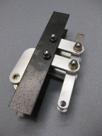
Here are some lugs for the shocks' bottom rod ends;

IMG_4840.jpg


The top end of the shocks were bored larger rubber and brass bushes were fitted to add a little "give". Any advice on bleeder valves?

IMG_4836.jpg


Steering linkage;


IMG_4841.jpg


The top differential mounting plate was chopped up and an aluminum doubler was added because I had doubts that I could get it out after everything was welded up; It's pretty hard to see, but the top steel plate is in three pieces.


IMG_4839.jpg


Our youngest son turns one tomorrow, they and our home keep me pretty busy so stay tuned.....


Cheers, KB
 
how bout some brake bleeders out of a couple of old brake calipers or for something smaller idle mixturer screws out of and old holley 2 or 4 barrel carb your build is looking good dude keep it up and good luck
'


doug
 
Back
Top
AdBlock Detected

We get it, advertisements are annoying!

Sure, ad-blocking software does a great job at blocking ads, but it also blocks useful features of our website. For the best site experience please disable your AdBlocker.

I've Disabled AdBlock    No Thanks