Carson c5 looks like it needs some attention

This site may earn a commission from merchant affiliate
links, including eBay, Amazon, and others.
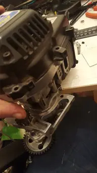
Well I quickly realised I was missing the 'special' bolts, a quick Google showed me I needed some bolts without heads and a nylock nut for each one so I piped to the local hardware store and bought some bolts then I preceded to lop the heads off with a dremel 20160316_133504.jpgI quickly realised that I would need to cut a slot in each one to get a flat blade screwdriver in so I could tighten them in which I did.20160316_133819.jpgSo after 10 minutes of faffing getting them all the right length I thread locked them all in place and installed the new housing 20160316_135234.jpg 20160316_140726.jpg
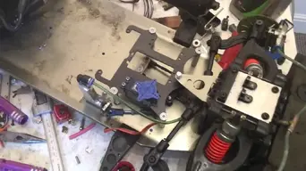
I think I did a pretty good job to say I'm no machinist and I'm certainly no engineer (even if I like to think I am) so now I have a new issue, in order to try and same myself some money I did not order the ally engine mount for the other side as I thought the plastic one would do the job, I was wrong. The plastic mount is slightly (maybe 1/2 an inch?) Taller than the new one so I have no idea what to do? Can I shave the excess plastic off or will that damage the integrity of the mount, should I space the new mount up a bit with somthing? But them I feel like I'm inviting more problems. I know in my heart the answer is to buy the other engine mount and suck up the pain it leaves in my wallet, I was just hoping to get it on the road again today :(
 
Well I went back to measure up exactly what the difference is and it looks like it's 10mm out. Then I looked at the plastic mount and spotted this.Snapchat-2169901649114222807.jpgExactly the same size as the standard mount hole and who wants to wager a het on how much lower it is (centre to centre) yep exactly 10mm, so I'm thinking if I drill through there then the back of the engine Will mount to there and since the quick mount can rotate I won't have any problems with it being twisted, I could be wrong but at this point the plastic mount is about to go in the box of old parts so it's worth a try right? Unless anyone can point out a flaw in my logic?
 
Well I went back to measure up exactly what the difference is and it looks like it's 10mm out. Then I looked at the plastic mount and spotted this.View attachment 10694Exactly the same size as the standard mount hole and who wants to wager a het on how much lower it is (centre to centre) yep exactly 10mm, so I'm thinking if I drill through there then the back of the engine Will mount to there and since the quick mount can rotate I won't have any problems with it being twisted, I could be wrong but at this point the plastic mount is about to go in the box of old parts so it's worth a try right? Unless anyone can point out a flaw in my logic?

I was wrong, this did nothing haha I see what I did wrong but now I'm stuck I have no idea how to make this work, maybe a 10mm rect angle under the new ally mount? However I'm starting to think somthing is up, it seems to me that the whole thing is 10mm to high, as the mount that would normally go through the rear brake connecting to the diff is also too high but as it is all one sealed unit I assume with lower mounts it would work.
 
Well this is how it sits as I'm at the end of my tether for today.Snapchat-1077906384687486502.jpgThe new mount (left) is sat on top of a ride hight gauge that measures 10mm and the engine is sat level, if anyone has and tips/suggestions I would be happy for the help as I am now stuck. To me the ally mount for the other side looks identical the the standard plastic one so am I right in thinking that would also be 10mm too tall?
 
that I don't know I think theres different ones ive come unstuck before brought one and was to thick sit the engine on level surface as you did before then work out thickness
 
that I don't know I think theres different ones ive come unstuck before brought one and was to thick sit the engine on level surface as you did before then work out thickness
Thanks for all the help man, I knew you would know somthing about this haha, I found one on ebay cheap, I don't know if it's the right thickness or not I will message the guy and ask if he can measure it, if it's wrong I'll make one.
 
Well it's all mounted and looking pretty good, now I have to tackle the next issue on my list, the brakes! As it was the stopping power was pretty feeble, but now the new gear carrier dosent have a layshaft brake and the front cable disc's really aren't up to it especially without the layshaft brake assisting.

since I don't have the money to upgrade to hydros at the moment I have just ordered some 68mm fibre discs as they apparently have more stopping power. Tomorrow I'm going to have a look at the radio plate, sicce I have some ally plate lying around I'll see if I have any big enough to make a radio plate that's a little stiffer. Am I better going for a standard size hi tourqe servo or a large scale one?

Any more tips on getting a bit more stopping power out of them?
 
well i have more pictures, the car has been sat on the bench getting little bits of attention here and there. so i took the plunge and ordered some hydro brakes for the front, they have been sat on the desk next to the car for a week or so as i really didnt want to have to strip it down to put it on the drill press and drill the holes for the master cylinder, in that time i came a =cross a cheap used carbon radio tray. so after parts started piling up for it i took a dayto strip it put it on the drill and drill for the master cylinder and radio tray now they are all mounted and the brakes are fitted (after having to make some stupid mounting block things, also can anyone point me in the direction of a brand of these calipers?
WIN_20160602_19_39_04_Pro.jpg
 

Attachments

  • WIN_20160602_19_39_38_Pro.jpg
    WIN_20160602_19_39_38_Pro.jpg
    128.3 KB · Views: 4
Thanks for the help,that's a nice looking car! just trying to source some piston seals as one of them has a nick and is causing an air leak.


Also my rear brakes turned up today, another ebay bargin I'll take pics when they are mounted but after a bleed they seemed to be working great, which is more than can be said for the front set at the minute haha
 
Hey guys sorry to revive my old thread but I didn't see the point in making a new one, they car has taken shape since my last post but it's far from perfect.

Since the last post I've had a hell of a time fitting the hydros out of the 3 sets I bought I managed to get one working set and sold all the rest of the bits on the car now runs and drives around but has 2 distinct problems, number one is the lack of any form of rear brake.

Since I fitted the quick release gear carrier I could no longer use the layshaft brake, im going to look into a set of cables for the rear as the ones for the front don't seem to fit :/

Number 2 is it is coming out with a nasty grinding sound still from the layshaft/diff at high throttle, it's eaten 3 layshaft gears now so I'm assuming it's the diff ring gear seems warped/uneven one side seems to.mesh better than the other, I have a used one coming from eBay to give a go and if it works I'll invest in some blackbone ones.

Any way just wanted to update the thread here is a pic of how it looks now

6c1d33aa3e0f65d58fbbe2be2fbea3a1.jpg

On a side note does anyone know how to remove paint from a shell? I would like to repaint it but don't know how to get the old paint off
 
Last edited by a moderator:
Back
Top
AdBlock Detected

We get it, advertisements are annoying!

Sure, ad-blocking software does a great job at blocking ads, but it also blocks useful features of our website. For the best site experience please disable your AdBlocker.

I've Disabled AdBlock    No Thanks