hey guys how to use killerbee and oddified ecu together

This site may earn a commission from merchant affiliate
links, including eBay, Amazon, and others.

new-fg-owner

Well-Known Member
Messages
260
Reaction score
0
Location
london
hey guys i'm still abit confused as how to make the wiring to use the killerbee and oddified ECU at the same time. renbar has been fantastic and messaged me a few times to explain, thanks loads renbar :)

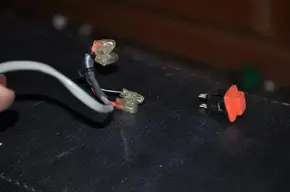
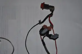
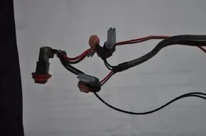
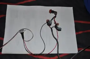
just wondering if anyone has any photos of this setup as im a visual learner and this would help soo much, also to show a picture of a spare killerbee lead with the red and black connectors at the top, to see if i can use these to solder instead of the tamiya 7.2v plugs.

im just really confused with the soldering etc i don't want to ruin the ecu lead or killerbee lead by cutting things and putting things in wrong place. so be ace to see a photo :)
 

Attachments

  • DSC_0062.webp
    DSC_0062.webp
    22.2 KB · Views: 24
if youve got that lead best thing or what i would do is fit lead as normal to the engine and cut it in half fit a male tamiya or deans plug,,,then the other end coming from your radio box join this and the ecu lead to the female plug they crimp so no soldering needed
 
ive just thought of an idea also, can i litrally just connect the killer be from the radio box via the grey cable as normal and litrally cut away some of the wire covering on the black and red wire and solder on the ecu cable means i then have to remove the deans pluc i think its called and remove the ignition connector for the ecu.

why am i finding this so confusing whats wrong with me lol. everything i just get a blank its like maths with me lol. on my killerbee on my fg is this the connector you mean renbar?

could i just put something inbetween this for the ecu?
 

Attachments

  • DSC_0065.webp
    DSC_0065.webp
    37.6 KB · Views: 19
ahh i see ok thats seeming alot more simples now, just a case of how i join the ecu between those connector bits. you probably said in your post up a bit im just being stupid prob and not realising. would you cut away wire on the engine side of the connector or litrally get something to go inbetween the two connectors.

ah lol everytime i think oh simples i confuse myself again haha
 
hey matey renbar and everyone looking. so ive got the ecu back today the lead from the ecu is just a red and black wire with no connector on the end of it.

my new question is where the killswitch connects to the ignition coil, red and black with those clear rubber things on the connectors. Can i just cut those connectors off and then solder the ecu wires and the wires for the killswitch back onto those connectors with the clear rubber things on them?

is that to simple or will that work im trying to think of the most simple thing and not be complicated.

be ace awesom great to see some of those photos if youve had chance renbar matey :)
 
hey guys ok here is some more photos, this is what i'm going to do to solder on the Oddified ECU wires onto the killerbee wires that go from the ignition coil to the killswitch button as you can see in the photos.

so i will solder onto that all i want to know is will this work and will i get current and power to make the ecu work. if i do exactly what i have shown in the photos? Thanks guys
 

Attachments

  • DSC_0069.webp
    DSC_0069.webp
    17.2 KB · Views: 11
  • DSC_0070.webp
    DSC_0070.webp
    17.7 KB · Views: 12
  • DSC_0071.webp
    DSC_0071.webp
    14 KB · Views: 10
  • DSC_0072.webp
    DSC_0072.webp
    14.6 KB · Views: 13
  • DSC_0073.webp
    DSC_0073.webp
    17 KB · Views: 11
hey kent he said it litrally just crimps or solders onto the apporioate cables so red for red and black for black.

the car came with an adapter which runs from the ignition coil out to connect the ecu via a red plug, think its a deans plug or fg battery plug.

thats just attathced to the killswitch button to the metal plugs like i have shown in the photos. im trying to work out how to bleed contrast neox brakes now very confusing
 
Back
Top