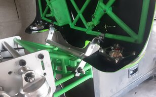
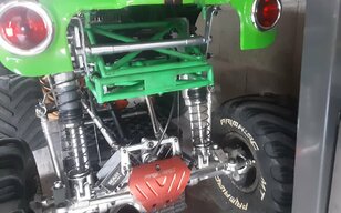
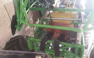
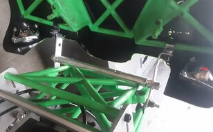
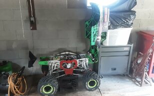
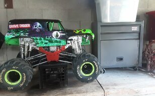
I have pictures in my gallery but cant figure out how to send to you.Shows what I did to not cut cage.if you can work me thru i ll send.I tried to gmail to https://www.largescaleforum.com but showing me invalid site.....
Navigation
Install the app
How to install the app on iOS
Follow along with the video below to see how to install our site as a web app on your home screen.
Note: This feature may not be available in some browsers.
More options
You are using an out of date browser. It may not display this or other websites correctly.
You should upgrade or use an alternative browser.
You should upgrade or use an alternative browser.
Another Taylor 50GT “Grave Digger” Engine ….
- Thread starter Shad0man
- Start date
This site may earn a commission from merchant affiliate
links, including eBay, Amazon, and others.
links, including eBay, Amazon, and others.
- Thread starter
- #22
That would be appreciated Mick, thank you.
Did you want to openly share with all or discreetly share ?
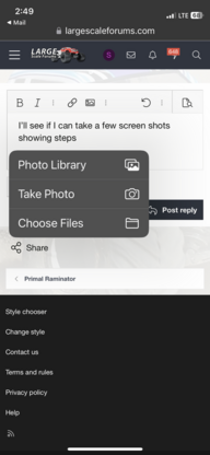
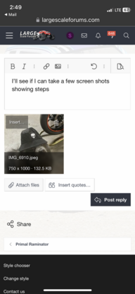
If openly with all, you should be able to start a reply and then below the reply text box and “before” you submit your reply select attach files. Then you can select the pictures that you desire to share. After this you’d do as normal and select post reply.
That would be appreciated Mick, thank you.
Did you want to openly share with all or discreetly share ?
If openly with all, you should be able to start a reply and then below the reply text box and “before” you submit your reply select attach files. Then you can select the pictures that you desire to share. After this you’d do as normal and select post reply.
- Thread starter
- #24
Hi Mick
It looks like you tried.
As I recall, after you select the pictures you want to share there is another selection for submitting multiple below the pictures.
At this point you can simply select the edit button which is found by selection the “…” three dots and there will be a drop down with the edit option rather than initiating another reply.
Once you do it successfully the first time it will become easy.
Thank you
RCSteve
Well-Known Member
- Messages
- 86
- Location
- Sacramento, CA
Might be too many pictures try only fourWill try .I am hitting paper clip,selecting images,selecting all but not letting me come back to send
- Thread starter
- #27
OK on android tablet after selecting images,all,wont let me go back to forum .Where is 13 year old grandaughter when l need her..... I will figure out and send,nothing fancy but my prototype might give you a starting point to keep from cutting..... has survided several roll overs and I can see you will be able to run with from your fab skills
- Thread starter
- #29
Fancy is a subjective term.
Form follows function is a quality of this hobby. As you stated long ago, this modification works for you and it could very well work for myself and others too. If fancy is desired by any or all you will have shared a tested roadmap.
Very cool Mick
We look forward to your granddaughter helping you get the pictures uploaded.
FYI, I use Windows or iPhone and the process is painless. I’ve never owned an Android so my knowledge is nil.
- Thread starter
- #31
Mick, you had me to busy to shave today

It is awesome that you got the picture submission figured out, and even more so, that you are willing to share.
Your Grave Digger looks very cool. You put much thought and work into the transformation. I like how the body simply tilts forward.
IMO, the fact that you shared your personal project are the fundamental building blocks of a quality RC community.
I give you your first, “Thank You”.
- Thread starter
- #34
Progress ….
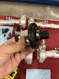
I reassembled both diff following John Parks upgrade system however, with a slight twist.
I opted not to use Nylocks. I have them I on hand but after much consideration I decided to use lock washers, conventional nuts, and Loctite. Only time will tell if the diff assembly stays stable after being exercised.
My reasoning is as follows.
1. The lock washer will allow for minor surface deviation where the nuts reside in case after grinding for clearance it’s not perfectly flat at the nut face area.
2. A conventional nut is by design, able to be used with Loctite whereas Henkel does not recommend it with Nylocks. Furthermore, I have read where folks have disassembled their diffs and found the Nylocks were no longer tight even when Loctite was used.
In any case.
I methodically assembled the diffs with 1M oil/paste in the cup before sliding the pre-lubed spider gears and shafts into position. Then I rotated the spider gears a several times over a 24 hour period so the thick oil migrated throughout and gassed off.
Once the oil was clear, using new diff gaskets, Loctite, and cross torquing the hardware they were both assembled. Now after 24 hours of curing the rear-ends will be ready to be assembled with some Fast Eddy grease on the ring and pinions.


ShadOMan did you strip red anodize of your diff housing or do you have a v3 truck?I am curious because all the diffs I bought were red.If you have a v3 diff it may have the upgaded diff cups already,suppossed to be stronger than v1,v2.I am thinking primal is selling v2,spiral cut gears as replacement,not v3s.V1 had straight cut gears.Might be worth asking Dan.I just ordered parts,including a v3 f/w shaft,showed in stock in taylor upgrade parts,then got email stating out of stock,got a refund for shaft,a bit confussing.Web site says taylor diff cups in stock too if you are still waiting.Perhaps web site not up to date????
Have not broken anything so no diff check.Let you know if nylocks with drop of superglue holding.When i groung housing I got the spot where not sits flat,so might last.Watched some great videos of lockwashers,star washers,etc.all of them worked loose......don't know if the nordlocks come that small.They are the only thing that we used in heavy apps for steel or mineing equipment.
Just checked nord lock website m4 pack of 20.,17 bucks....going to order a varity of sizes for future use
Last edited:
- Thread starter
- #36
Hi Mick
Good day and thank you.
Taylor diff cups will be here any day. I initially held my order with Primal waiting for the F/R synchronizer shafts. Like you I made the order for Taylor’s shafts and soon after it was refunded. Primal’s version 3 shafts remain waitlist only. Dan shared that they are out of stock even though the website implies otherwise. It’s a site glitch. I chatted with Mike Taylor and his should be available soon.
Yes, mine is a version 3 Grave Digger Collector’s Edition with the upgraded V3 diff cups nonetheless, I opted to order Taylor’s parts. Mike Taylor has a Grave Digger with his 50GT engine installed and shared that he broke diff cups, F/R synchronizer shaft, and both output shafts in the beginning. He was also quick to share that he blamed himself for landing under power which I understand. Nonetheless, having spares that may never be needed affords peace of mind when compared to breaking something and having to wait.
In any case.
As for my using a nut, lock washer, Loctite versus Nylock and Loctite or superglue, only time will tell. I hope both considerations work and remain stable. Earlier you mentioned that your Nylocks did not remain torqued, that when you opened your rear-end the Nylocks were loose but not falling off, my words not yours. So, my fingers are crossed that the superglue was the fix for you. I considered using Nord locks because I use them in other applications but because they are 9mm diameter, roughly 2mm larger in diameter than the nut and or Nylocks that are both 7mm diameter I was concerned about removing more diff housing material and furthermore, they will extend past the outer edge of the diff housing roughly 1.5mm. I am very interested in your experience with them because they are “great”.
I also observed that the diff cups do “not” index tight on the spur gear within the diff housing. With the button head screw only slightly loose the diff cup can rotate back and forth a little. The assemble only becomes one once the button head screw is tightened. This means that forward/reverse torque can result in the diff cup button head screw coming incrementally loose even though it likely won’t ever come out. IMO, once the diff cup becomes loose I suspect that the diff cup shaft becomes the centralized point of stress as such is more susceptible to snapping. If there was no slop between the diff cup shaft and spur gear the torsional stress would be as an assemble and would be spread out over a larger area. No science behind this, just my thoughts.
FWIW, I ordered 2 spare diff housings that I am going to fixture them in the mill and drop an end mill down to create the clearance. I think doing it this way I can get more clearance and a perfectly flat nut face surface.
- Thread starter
- #38
Cool!!!
I want to see you rig in real-time with the body lift and custom opening system.
Now back to my comment regarding securing fasteners and what are considered the best.
The correct answer has many variables as well as subjectivity. Nonetheless, here is one mechanical opinion regarding hardware in the most general sense.
Remember, the objective is the constant with the “how to” achieve having many different paths. Collectively we will all ultimately define the path that works best for this particular situation.

- Thread starter
- #39
More progress …..
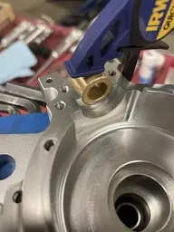
To be very clear, I like John Parks sintered bronze bushing upgrade for the pinion shaft “very” much. A big thumbs up to John. I reached out to John regarding securing the bushing so it does not spin during operation. One wants the shaft to spin within the self-oiling sintered bronze bushing and not have the sintered bronze bushing spinning within the rear-end housing which ultimately could cause wear within the housing. I pursued this thought because I found that during my test fitting that once the rear-end halves are assembled that the sintered bronze bushings are not a compression/pressure fit but rather they can still move freely. The fit is so very close, maybe .002-.003 clearance, and yet, there is just enough clearance to allow the sintered bronze bushing to “potentially” spin.
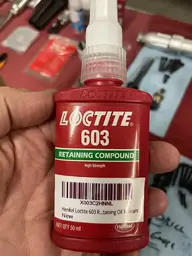
I gave it much thought wanting it to be an easy process to secure the bushing by anyone that deemed it important while also retaining the ease of future servicing. Initially I was going to pin drill the case and the bushing and use a tiny ball bearing to index the bushing to the case but opted for a far easier path. Henkel created Loctite 603, a product designed specifically for retaining and stopping sintered bronze bushings from moving/spinning so I decided this was the way to proceed.
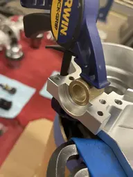
After speaking with one of Henkel’s engineers I decided to secure the bushing within only one half of the rear-end. I cleaned the cavity in the rear-end and the sintered bronze bushing with acetone and then applied the Loctite 603 only to the side of the bushing as shown seated in the rear-end housing half and then clamped it in place as it will remain for 24 hours. I am “fairly” confident that doing it this way will insure that the bushings won’t spin while also insuring that it remains very easy to service the pinion, pinion bearings, and also replace the bronze bushing if necessary.
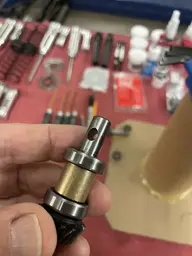
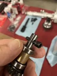
During this process I also had to hand file the pinion shaft in the area where the driveshaft securing pin hole is because even after only moderate use that area was slightly distorted making sliding the pinion shaft bearings on and off challenging. This occurred because the pinion shaft through hole is slightly larger in diameter than the diameter of the bolt that secures the driveshaft as such, once the driveshaft is secured in place it can still rotate ever so slightly back and forth during operation which causes the hole in the shaft to flare at the center of the through hole. I do not anticipate this to be a pervasive issue since tended to.
In closing, most of what I do is “not” needed for me or others to enjoy these rigs but rather things that I enjoy doing. IMO, they are often simply personal touches and a cool way to incrementally improve Dan’s already spectacular platform.


- Thread starter
- #40
Just a quick update.
I tested how secure the sintered bronze bushing was after using the Loctite 603 on only 1/2 of it. I applied it to only 1/2 of the sintered bronze bushing so that disassembling the rear-end would remain easy.
After several tests the sintered bronze bushing remained firmly in place. Then I removed the sintered bronze bushing and then reinstall it to confirm a real time experience.
It required my small butane torch using an hot air heat tip primarily focused in the lower inside of the sintered bronze bushing to get it to come free. It did not require extreme heat. Once it was free the machined pocket in the rear-end and the bushing looked perfect. I cleaned both surfaces with acetone again, applied the Loctite 603 on 1/2 of the bushing, set it back in place and clamped it.
This Loctite product sets “very” quickly but requires 24 hours to fully cure.


