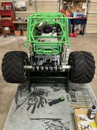
Another Taylor 50GT “Grave Digger” Engine ….

This site may earn a commission from merchant affiliate
links, including eBay, Amazon, and others.
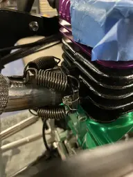
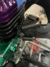
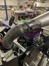
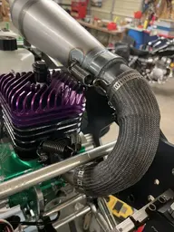
The exhaust is finally secured.

Mike sent me a couple cross drilled header flange bolts and I wire tired them to secure the header flange. While the header pipe was off I decided to detail my thermal sleeve. I folded it under itself to create nice crisp finished looking ends rather than the frayed ends in my previous pictures and I also decided to use positive locking stainless straps rather than the stainless wire.

IMG_7459.jpeg

IMG_7460.jpeg

IMG_7465.jpeg

IMG_7466.jpeg
 
Last edited:
Hi Rceverywhere

I agree, Dan created a piece of mechanical art and I have done my best to compliment his vision often by following the path of those in front of me.

Absolutely it will be exercised and enjoyed.

Your kind words are appreciated.

Thank you.
 
A long rambling to follow… get your personal flavor of the day and sit back.

Last night and today I spent time to understand why the negative pressure reservoirs all weep at the Allen cap screw adjuster, even when the rig is simply sitting on stands albeit periodically being bounced around. Seeing this there is no doubt that when the rig is being exercised that it could only be worse.

Dan and I have discussed it with no definitive path defined to correct and John Parks and I discussed it too and he’s simply accepted it as the reality for now.

First of all, initially I shared with Dan that I felt a positive seal rather than an o-ring could be considered however, this was before I took them apart now understanding the why. First of all, by design the o-ring is simply a token friction point for the adjuster screw and not used as a seal. A short section of rubber tubing or wading material that was pressed into bore would likely produce better results, just a thought as I have not tried it “yet”. The idea I just shared is a practice common with carburetor mixture adjusting screws, etc..

So my thoughts as shared with Dan.

1. “Assuming” that there is a need to seal the adjuster threads the adjuster screw threaded into the cap is problematic. The screw should be able to turn freely with a positive seal to simply to seal the shank of it. In doing this the plunger would need to be threaded and move up and down by turning the screw. Easy enough concept but to do so the plunger would have to be keyed so it did not simply spin freely with the adjuster screw too. Well, so much for an easy fix.

Then I removed the negative pressure cylinder pistons to check the seals because “if” they were doing their job no oil would get past them to drip out. I immediately noticed that the orientation of the seals, albeit proper in both mine and John Parks opinion and as shown in the Grave Digger owner’s manual were installed 180 degrees different than the way Owen from Primal said they need to be in his video so I stopped and asked Dan. He said that he asked Owen and that Owen found that they seal better in the unorthodox (my word;LOL) orientation. I shared this with John too and through the text I could see him shaking his head nonetheless, I decided to follow Dan & Owen’s directive as I have been surprised before. It also gave me a good excuse to disassemble all the shocks and dampers to simply inspect how they were assembled; LOL.

Here is Owen’s video. He shares some good points.


One by one I disassembled the negative pressure cylinders and rotated all the seals 180 degrees.

The other thing I did was initially fill the negative pressure reservoirs with the piston down in the bore 1” as Owen and states in the video and then tested the first shock before proceeding.

Immediately a couple issues were encountered.

1. If you fill the negative pressure cylinder with the piston down in the bore 1” and then fill the primary cylinder you will loose roughly 2” of the shock/dampener compression stroke. However, if you fill the negative pressure cylinder to the level Owen graphically shows rather than as he states in the video the piston is actually only roughly 11/16” down the bore and then fill the primary cylinder it works well with the shock able to be compressed by hand with modest pressure to roughly 3/4” from bottoming out.
2. Owen’s also shows how he puts oil in the negative pressure cylinder while they are fully assembled in his video. For those that have not done this I can share first hand that the simple act of pressing the piston down against the spring hoping to get the piston to garner some friction against the cylinder bore and stay in the same place on each and every one is to be blunt; laughable because at best you hope that it will stay and then he adds the oil. There is no reason for this and in fact, it makes it truly impossible to put the same amount of oil in every negative pressure cylinder as such it’s impossible to balance your shocks and dampeners.

The “very” easy way to do this is don’t install the spring, plunger, and end-cap until the shocks are “fully” assembled as the piston has 2 seals on it so oil should never pass it, particularly, in a static condition. To be clear, you put the spring and plunger in, and end-cap on “after” the negative pressure cylinder and the primary cylinders have been installed. Like Owen I found installing the negative pressure cylinder first was easiest. In any case, sad to be clear; with only the “bare” negative pressure cylinder in your hand simply slide the piston down the bore to the depth of 11/16”, add the oil, screw the cylinder onto the cap, fill and install the primary cylinder, turn the shock/dampener assembly over and install the spring, plunger, and cap and you have completed the process with no stress and the oil level in every negative pressure cylinder and primary cylinder are the same.

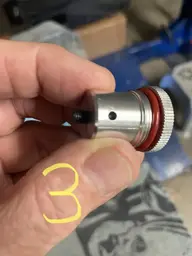
The last oddity I found was a cross drilled hole in the negative pressure cylinder end-cap. It’s primary purpose I do not know, I sent Dan a message but have not heard back. In any case, this is where the oil weeps out and appears as if coming from the adjuster screw. The oil is not going past the threads. The only way oil can get to this area is by passing both of the seals on the negative pressure piston.

As the result of this revelation.

I think the real fix is easy and requires 2 things.

A pair of better seals on the negative pressure piston and a stiffer piston spring to insure that the piston and the oil transfer between the primary cylinder and negative pressure cylinder are constantly working as one. As it is now there are times that the negative pressure piston will stick in the bore creating an air pocket just as Owen shows in his video how he the sticking piston as the means to fill them with oil and when this happens the shock dampening become significantly less, even if only for a moment.

As for the cross drilled holes in the end-cap. Unless explained I see no value in the cross drilled holes in the negative pressure end-cap.

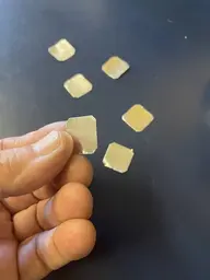
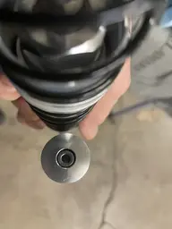
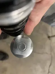
Lastly, I want my suspension very compliant so I have the negative pressure dampeners as soft as they can be and since I don’t plan to make regular adjustments I have sealed the bottom of my negative pressure cylinders. I used a very tacky thin metal tape cut into 3/4” squares. Even if oil were to rest on it the material would not be affected, the “only” question that remains is how badly the negative pressure piston seals actually leak because if much, with the oil that passes will come pressure too so we shall see. If pressure passing the piston does not become an issue the other benefit to this is the adjusting screws can’t fall out.

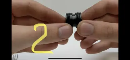
The pictures included are marked as a point of reference.
Number 1. Is the negative pressure piston that I removed before re-orientating the 2 seals.
Number 2. Is a screen shot taken of Owen’s orientation of the seals as presented in his video included above.
Number 3. This is a picture of the yet to be understood cross drilled holes in the negative pressure end-caps.

The final 3 pictures are simply my sealing the negative pressure end-caps.

IMG_7500.jpeg

IMG_7501.jpeg

IMG_7502.jpeg

IMG_7504.jpeg

IMG_7507.jpeg

IMG_7509.jpeg
 
Last edited:
Locktite them both or they will fall out........and leak.Not to talk down on primal but it a show no go setup.Get the newest seal kit,they are basically a automotive valve stem seal,they don't leak,period.And yes my shocks all had upside down seals and leaked in package.Fully extend shock,fill em to top,cap em,run em.We have to accept that these are not REAL SHOCKS.I at one time was living in rc fantasy world,custom this ,aftermarket that.Run em hard,break em,figure out why it broke,then don't do it again.....EG don't hit the house and you don't break the bumper....woops.Go run your truck and have fun,I eased up a bit and haven't broke anything after our discussions.These primal trucks are amazing,super tough,super fun,enjoy it ShadOman !!!!!.You have the best stuff on it now go play and have fun my friend!!!!!
 
Thank you Mick

As you stated, these are not real shocks when compared to a full fledged automotive shock, nonetheless, they are shocks designed to operated within the constraints of a 80lbs rig. Now whether real as you stated or a placating facsimile does not change the fact that they should not leak.

FYI, I was able to get the negative pressure reservoirs not to leak at the adjusting screws if I did as Dan suggested. He said to screw the adjuster screw all the way in so the o-ring was compressed at which point it also covered the cross drilled holes. The issue with that adjustment position for me was it made the shocks and dampeners stiff as if struts with very little motion whereas I want a more compliant shock so the suspension has some articulation when climbing over rocks, obstacles, etc..

Mick, I am glad that simply using blue Loctite worked for you. I put a little trace dye in the cylinder and I did evidence oil passing the threads, only through the holes. Sounds like your o-rings are now compressed based on your adjustment so they are blocking the cross drilled holes too. Regardless, very cool!!

Previously I did as you said and properly orientated the lower shaft seals as they were in upside down and with all shafts leaking and installed the upgraded end-cap with the automotive style seal and now the shafts are all dry.

As for Primal and it being all show no go, ugh… I think that’s a little harsh. They are a 80lb piece of mechanical art that as you’ve experienced are a blast but I do not think they were designed to compete with true bashers that fly like birds through the air. The are more of a scale depiction in looks, design, and their intended usage. This is not to say they won’t fly like bird as evidenced by many and frankly withstand extreme brutality but….. maintenance and repairs will follow no different than the real monster trucks. As you know very well, the HPI Baja’s and 5T’s as well as all that followed created a completely different platform for the true bashers.

They all live in the same garage but play in different arenas.

In any case.

Mick, you have done some very cool tweaks and personal touches to yours and shared them in detail so others can benefit too. I am glad that you are now enjoying it as it has remained issue free.

As always, I appreciate your suggestions and shared experiences.

In the end, there are many many BADASS RCs to choose from and without meaning to sound like I am marketing for them, there is only “1” Primal RC and I doubt anything comparable will be brought to market by another.

Takes care.
 
I lost two of the adjustment screws on my piggy backs and they never leaked lol
I did use green slime when I put them together so maybe that helped
I made rubber washers by using 1/8 thick rubber matting and using a 9.3x62 case as a cutter. I used a Lee case guage holder and lock stud so I could put the case into a drill chuck
After I had four rubber washers cut I used a 17 cal case to cut the center hole for the bolt
The bolts now go in with a bit of resistance due to the washer contacting the outer edge of the hole in the piggy back but I think using a 10mm case would make it a touch bigger and then seal a bit better too
I tried a 44 mag case and the washer was too big
If your having leaking issues this should help plus it will stop the bolts from rattling out
 
Thank you deathrawt

The fact that they fell out and still did not leak means that your pistons were sealing properly.

I like your alternative to the o-rings.

Good job
 
Thankfully none of mine leaked, but I did almost lose a couple of those adjustment screws. I did the same and just used tape to keep them from falling out. The negative pressure caps are gimmicky, they don't do a thing outside of look cool as none of them work as smoothly or the same as the others. Getting these shocks all evened up on rebound is an exercise in extreme patience, and even then the negative pressure caps will work differently so it'll never be the same regardless.

Some of the negative pressure caps, the seals and fit is so tight the spring doesn't have enough tension to push the pressure cap back up, some work smoothly, most are somewhere in between where they may move smoothly while still maintaining a seal after some amount of break-in period.

The inner walls of my shocks, maybe 1 or 2 were smooth, the others had scratches and/or 'rings / grooves' from machining and like they forgot to finely hone the bore. The shocks overall are a hunk of junk, and if you're really paying attention you'd notice the issue with the improper setup with shock shaft bushings and how much play there is side to side etc.
 
Hi codeman11

I observed the same when I disassembled them. I found that the piston in 3-4 out of eight would stick in the bore and not move freely with the remainder somewhere between occasionally sticking to so loose that oil passed by the seals.

Like you, I think they look cool but far from consistently functional. For example. If the shock is fully compressed and the negative pressure piston remains stuck down the cylinder the dampening in that shock is severely reduced. At the very least stiffer springs are needed to insure that the negative pressure pistons are always at the top with the oil being the common that moves the piston up and down against sufficient spring pressure because without their operation is interesting at best.

Thank you for your comments and fir sharing your personal experience.

Takes care
 
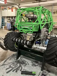
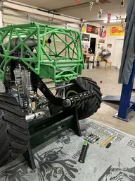
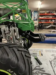
Another great addition arrived for the Grave Digger from Dan and the Primal Team today, their new wheelie bar setup.

I saw these being tested in one of his videos about a year ago and liked what I saw. The wait was worth it.

It was easy to assemble and install and IMO looks great except, subjectively speaking, the silver washers that I will change to black. The grouping of the 6 small diameter wheels, each with a pair of sealed roller bearing looks cool and IMO better proportioned when compared to the other wheelie bars that use a couple much larger diameter wheels.

Enjoy

IMG_1606.jpeg

IMG_1607.jpeg

IMG_1608.jpeg

IMG_1609.jpeg
 
They definitely look good, they will bend back also to being the material they are made from which is nice. I think they should definitely be thicker, but it's a start atleast
 
Hi John

Thank you for your comments.

I think they are a great piece.

They are stiff for the purpose of wheelies and yet are forgiving of side loads.

Far better IMO than aluminum side bracing that will bend.

Takes care.
 
Hi John

Thank you for your comments.

I think they are a great piece.

They are stiff for the purpose of wheelies and yet are forgiving of side loads.

Far better IMO than aluminum side bracing that will bend.

Takes care.

I've seen a few bend pretty bad already, as long as they can bend straight again shouldn't be issues. I know most made from the same materials are able to be bent back with a little heat
 
Back
Top
AdBlock Detected

We get it, advertisements are annoying!

Sure, ad-blocking software does a great job at blocking ads, but it also blocks useful features of our website. For the best site experience please disable your AdBlocker.

I've Disabled AdBlock    No Thanks