
- Thread starter
- #21
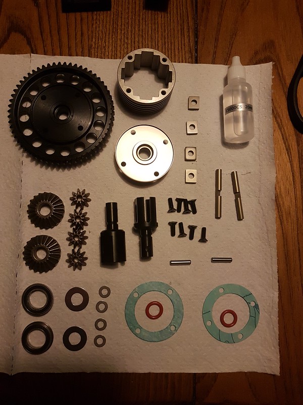
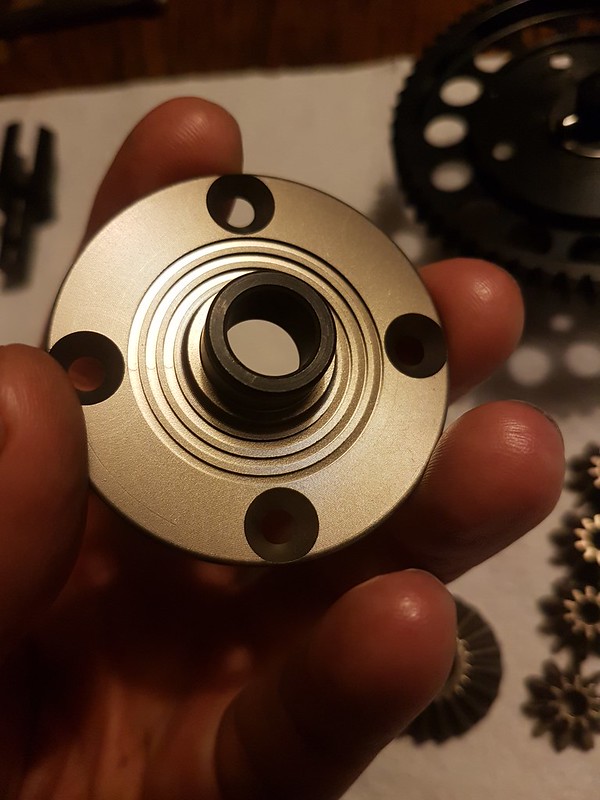
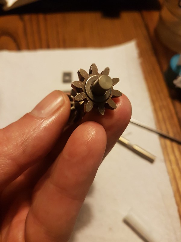
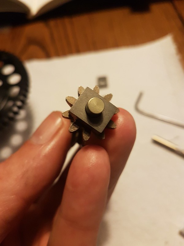
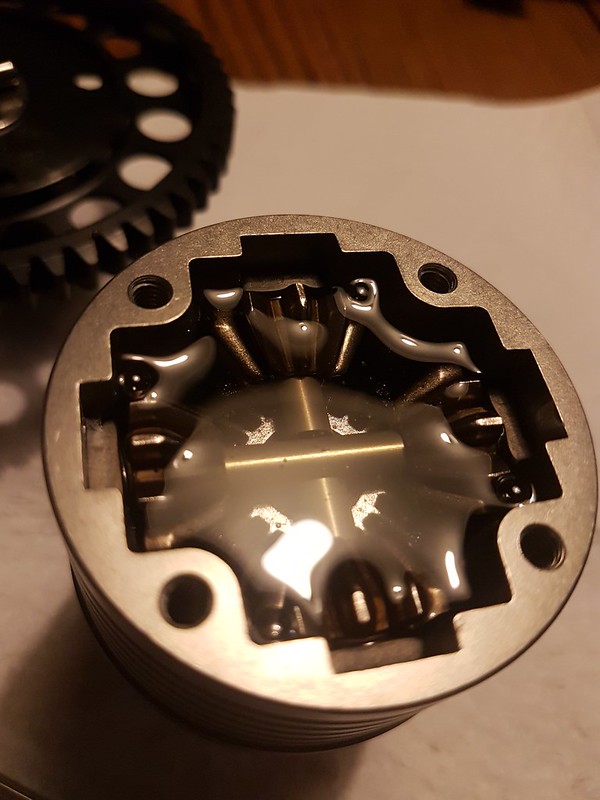
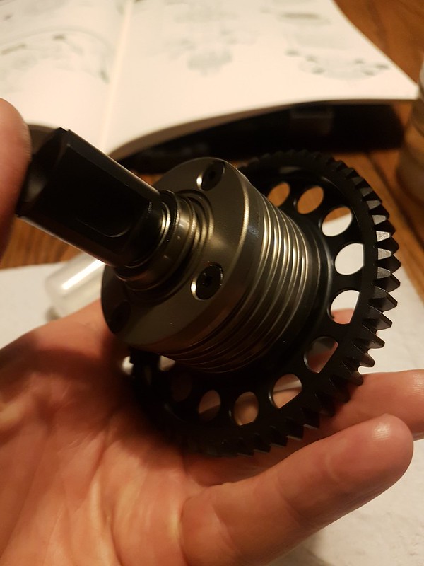
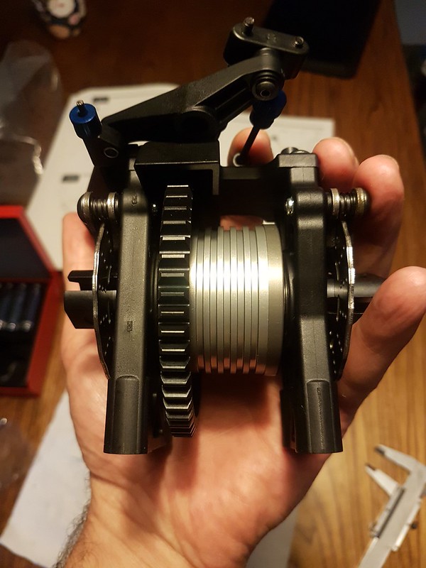
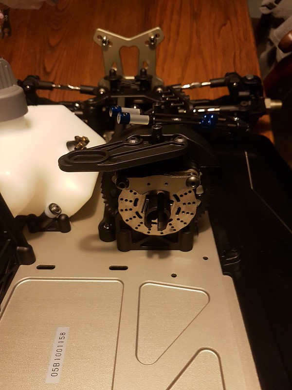
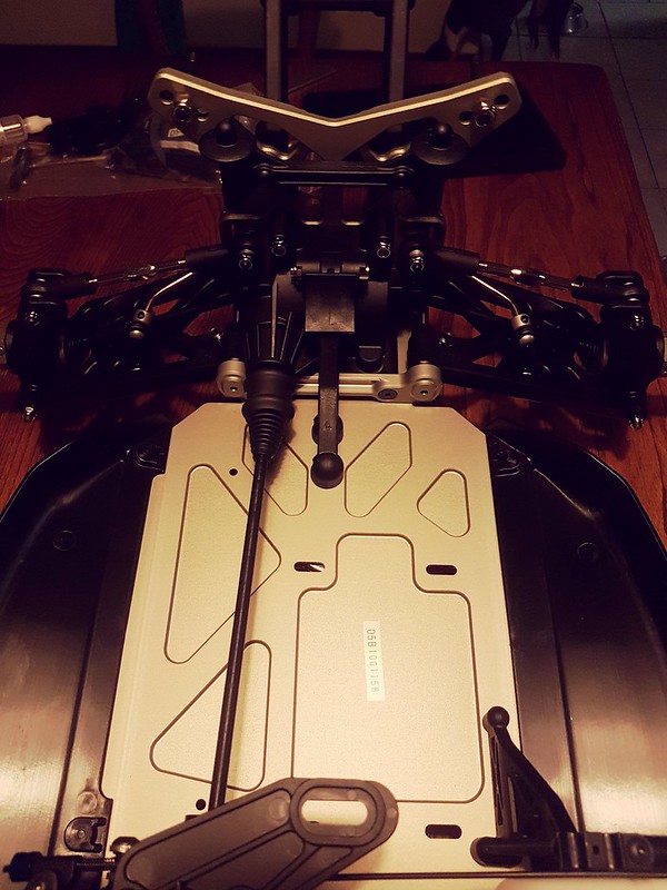
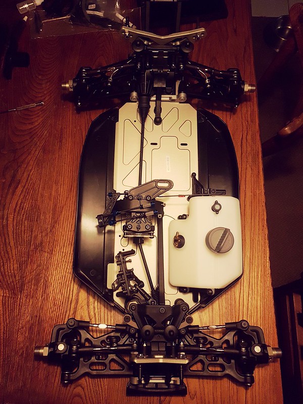
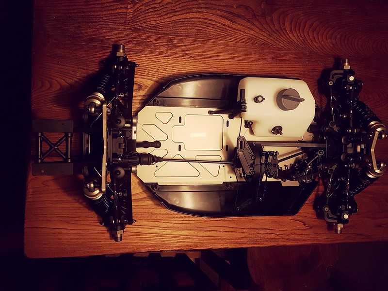
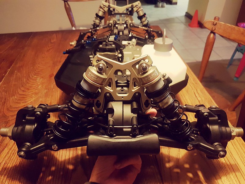
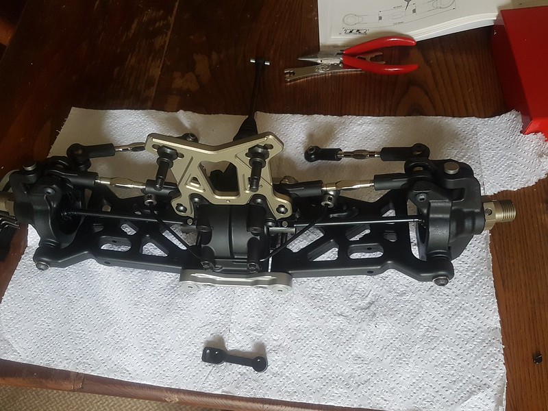
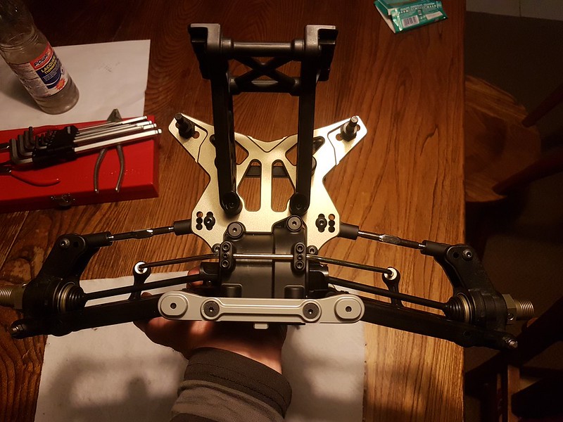
Im surppized after building the front and back diffs @ the sound that comes from the spur and pinion gears meshing as you turn the dog bones. its definitely louder than i was expecting. that being said i never built a 1/5 scale before, the only diff and transmissions i have had anything to do with were on 1/1 cars. but hey ill never hear it with the g320 and bart pipe screaming
")


")